BACKGROUND INFO, LEGAL ASPECTS, CAREFULNESS ETC
(things which are supposed to be understood and not
repeated with each new elsketch project page)
http://www.stamash.com/secs_stamash_educational_centers/elsketch/
OVERVIEW OVER ONLINE AVAILABLE ELSKETCH PROJECTS --
http://www.stamash.com/secs_stamash_educational_centers/elsketch/sitemap/
-- THESE HAVE ALL BEEN CAREFULLY STUDIED IN REAL LIFE,
NOT JUST AS AN EMULATION ON A COMPUTER, AND FOUND TO
WORK AS PROMISED; NOTE THAT SUCH AS AM MW RADIOS IS
-- FOR ANY LONG-RANGE USE -- EXTREMELY TIED UP TO
ALL SORTS OF WEATHER CONDITIONS AND THE EXTENT TO
WHICH IT IS NIGHTTIME
___________________________________________________________________
___________________________________________________________________
___________________________________________________________________
___________________________________________________________________
___________________________________________________________________
___________________________________________________________________
For the G15 Multiversity: Background works
Also part of the Stamash Educational CenterS, SECS
For general info about G15 Yoga6dorg see also www.norskesites.org/fic3
In general terms, we might use the following
vocabulary: Each Elsketch project constitutes
also a report over successfully completed
electronics development and implementation work,
in a sense a bit of 'neopopperian research',
intended to be replicated in an improvised,
intuitive, playful way by anybody who likes
to educate herself in this way.
This report is dated September 4, 2013. For
general info about copyright confer the spirit
of honoring acknowledgements as found in our
www.yoga4d.org/cfdl.txt.
___________________________________________________________________
___________________________________________________________________
___________________________________________________________________
___________________________________________________________________
___________________________________________________________________
___________________________________________________________________
Elsketch: Simple Intercom Buzzer
-- A module with adjustable tone giving an
intercom buzz type of sound as input
to a premade audio amplifier
 [note: for ease of composing the materials, frequent mentions
in the Elsketch texts are made of things which belong to the
future -- future Elsketch activities include making even a
whole G15 computer, and parallel activities are also referred
to in the same manner, such as the chemical educational activity
we have named Atomlite. apart from these references to things not
yet done as if they have been done, each elsketch project describes
a project actually carried out to success, and well tested, and
fully doable in the present by following the instructions.]
ICOMBUZ1: SIMPLE INTERCOM BUZZ OSCILLATOR MODULE
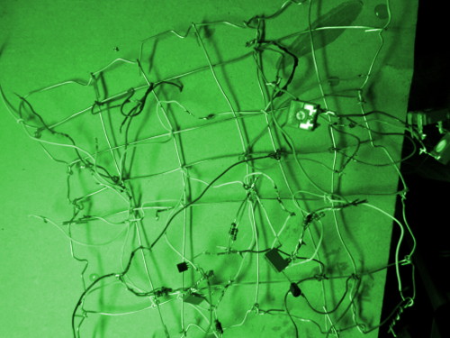
BEFORE YOU BEGIN, MAKE THE STEEL GRID
First, you make a steel grid as with the 1st radio
module. The steel grid is normally more stable if you
put the steel wires alternatively over and under one
another as you construct it -- with a sense of
'knitting'. Tie up variously colored plastic-isolated
thin steel wires (eg 0.6-0.7mm) of various lengths at
suitable positions intuitively decided.
COMPONENT LIST -- INTERCOM BUZZER OSCILLATOR MODULE
*** one premade audio amplifier module with its own
volume control, power supply, and loudspeaker, where
there are two wires that goes to this -- one for
ground, the other wire is main input
mentally tagged: "amplifier"
*** 12V power supply
mentally tagged: "power supply"
*** one NPN BC547C 45 volt or more transistor
tagged: "osc-1a transistor"
*** one NPN BC547C 45 volt or more transistor
"osc-1b transistor"
*** one 25k modulator (eg, twist four 100k in parallel)
"osc-1a power"
*** one up-to-30k adjustable modulator (eg, put
three up-to-10k adjustable modulators in series)
"osc-1b prepower"
*** one 25k modulator
"osc-1b power"
*** one 46.9 nf capacitor
"osc-1a c-pin"
*** one 46.9 nf capacitor
"osc-1b c-pin"
*** one 50k modulator (eg, twist two 100k in parallel)
"osc-1a m-pin"
*** one 50k modulator
"osc-1b m-pin"
TINNING INSTRUCTIONS -- INTERCOM BUZZER
Standard recommendations: Pls read comments after the
tinning instructions BEFORE tinning. Take extra care
with getting transistors and mf capacitors right.
Switch power on only after looking at the elsketch
very very carefully -- and then keep SAFE distance!
This is your own responsibility. Don't do it if
you're uncertain about the effects of doing this!
Use much light & magnifiers. Regard names of sections
of an elsketch as informal just like item tags. Check
tinnings by pulling a little on them and when in
doubt also check with an ohm-meter before power is on
(after short-circuiting any mf capacitors connected).
Remember that unless otherwise stated you can improvise
freely as to just how you tin something to something
else -- anywhere along a wire already tinned to one of
them you can un-insulated by the tinner, say, -- it's
not that you have to put more than one wire to each
component. Don't overheat transistors and such -- a
brief tinning to a wire, and let each cool before next
tinning. If a twisted pair of modulators (say) seems
not to be tight enough, it's best to tin them also.
* Get the POWER SUPPLY wires and be sure of which wire
is which, and get them tinned to suitable wires of
different color with some length on the grid.
* Tin GROUND WIRE of POWER SUPPLY to E-PIN of OSC-1A
TRANSISTOR, and also to E-PIN of OSC-1B TRANSISTOR.
* Tin MAIN WIRE from AMPLIFIER to C-PIN of OSC-1A
TRANSISTOR, and GROUND WIRE from AMPLIFIER to E-PIN
of OSC-1A TRANSISTOR.
* Tin OSC-1A POWER MODULATOR to C-PIN of OSC-1A
TRANSISTOR. Tin the other pin of this modulator to
PLUS WIRE of POWER SUPPLY.
* Tin OSC-1B PRE-POWER ADJUSTABLE MODULATOR (which
can be three in series, if you have our standard type
of 10k instead of one that is much bigger) to PLUS
WIRE of POWER SUPPLY. Tin the other pin of the
adjustable modulator to OSC-1B POWER MODULATOR.
* Tin the other pin of OSC-1B POWER MODULATOR to
C-PIN of OSC-1B TRANSISTOR.
* The OSC-1A M-PIN modulator is tinned between M-PIN
and E-PIN of OSC-1A TRANSISTOR.
* Similarly, the OSC-1B M-PIN modulator is tinned
between M-PIN and E-PIN of OSC-1B TRANSISTOR.
* Finally, let's get the capacitors to do their
holistic oscillation looping. Tin OSC-1A C-PIN
capacitor to C-PIN of OSC-1A TRANSISTOR. The other
pin of this capacitor goes to M-PIN of the
other transistor, the OSC-1B TRANSISTOR.
* And: Tin OSC-1B C-PIN capacitor to C-PIN of
OSC-1B TRANSISTOR. The other pin of this capacitor
goes to M-PIN of the other transistor, the OSC-1A
TRANSISTOR.
COMPONENT COMMENTS -- READ BEFORE TINNING
AS FOR TRANSISTORS
see the 1st AM MW radio description for C, M, E pins --
mentaly mnemonics for Collector, Middle pin, Emitter pin is
"CoMe Easy!" -- and this is the sequence that the data
work with the elsketch emulator on the PC has, it has
C M E as 1 2 3. Transistors, CoMe Easy!
AS FOR AUDIO AMPLIFIER
The most sensitive input pin to the amplifier is the main
wire, the other is the ground wire. The most sensitive input
goes to the C-PIN of the relevant transistor. If in doubt
which input wire is which, turn on the amplifier and with
somewhat loud volume then touch each of the wires in turn,
given that this is a safe low-voltage amplifier, of course.
Tapping the main wire -- the copper or steel of it, with a
very slightly damp finger, should lead to a tap in the
loudspeaker while usually no corresponding sound should
arise by tapping the ground wire.
[[[Mountable data app for input to elsketch emulator
in G15 comes as a link to a .zip here:]]]
YOU HAVE TINNED IT -- NOW GET IT UP!!!!!
Put the amplifier volume to the lowest possible and then
a little up. If you have put it together right, it will be
a remarkable buzz sound even on rather low volume.
Switch on power supply with only one wire tinned to the
elsketch (as usual the first time), and the amplifier.
Keeping your normal distance (always check out security
precautions eg as indicated in the main elsketch page)
try put the other wire to and see if it works, but only
after you've looked at the wiring and checked that nothing
is short-circuited there.
The sound is just right to get your assistants to connect
to you, their boss, with a properly obedient attitude when
you have clicked on your intercom. Its the type of buzz that
instantly demands attention, but it isn't unpleasant when
regulated to the right tone-height -- try adjusting the
variable modulator or modulators -- and with properly low
volume.
HOW DOES IT WORK?
The two capacitors -- some dozens of nanofarad are good to
make an audio frequency sound, which typically are in the
range of just some hertz and up to around twenty thousand
hertz, or 20 khz -- they act together with each their
transistor. We might put it like this: each capacitor plus
transistor interacts with the other capacitor plus its
transistor more or less as, in such as a radio, a single
capacitor interacts with a single coil in the context of
a transistor. So these two transistors are oscillator 1,
part A, and oscillator 1, part B. They are both part of
one single oscillator. So we tag them osc-1a and osc-1b.
The cut'n'dried description goes roughly like this --
it is probably rather boring to read, but stuff like
this has been written more lively elsewhere, so we allow
ourselves to do it quickly here:
One capacitor gradually lets through much then less and
less as it gets filled up; as long as it lets through
anything it acts to open -- also gradually -- the other
transistor so as to empty the other capacitor. This
emptying happens because the other transistor is connected
to the C-PIN of the other transistor. When the other
transistor is open, it lets through ground from E-PIN
to C-PIN, and thus to the capacitor -- it gets grounded.
But when the first capacitor is filled up, fully
charged, it stops the other transistor from being open.
This leads the positive charge at the C-PIN of the
other transistor to start flowing through the second
capacitor. But this flows acts so as to open the first
transistor, and so ground -- and empty -- the first
capacitor.
Now one of the transistors have the output stuff for
the amplifier at it. The other ones have the variable
modulator or modulators at it. If we are making a
different kind of tone with more balance between the
various motions of the sound waves, we would want both
transistors more equally handled as regards variable
modulators. Let's also get it said that only in such
low-power, non-urgent situations does it make sense to
have smoothly gradual variable modulators -- in any
high-watt situation, or any situation where it is
very important to have a stable result over time --
it is better to have fixed steps and a switch that
goes from one fixed set of modulators to the next.
A variable modulator usually have something like a
stretch of carbon on which a metal plate rests. This
stretch of carbon typically will get dirty after a
while and this will affect the tuning of it -- and
it will also make tuning at a much later stage (many
seasons later) likely to be a very noisy process.
So in situation where a more certain result is
called for, we use rather several fixed modulators
and a switch of some kind. This approach can also with
advantage be used where we could otherwise use a
sliding variable capacitor. In our quantum-inspired
philosophy, we should appreciate the value of fixed
steps and not have everything floating -- so that
'good floats' can happen WITHIN a meaningfully
created boundary of vibration, meaningful also
psychologically and spiritually.
The buzz sound is not only having a single
frequency, but also a kind of underlaying deeper
tone interposed on it, making it more a machine
sound and less just any tone in the surroundings
such as from a radio.
Best of lucks!
___________________________________________________________________
___________________________________________________________________
___________________________________________________________________
___________________________________________________________________
___________________________________________________________________
___________________________________________________________________
BACKGROUND INFO, LEGAL ASPECTS, CAREFULNESS ETC
(things which are supposed to be understood and not
repeated with each new elsketch project page)
http://www.stamash.com/secs_stamash_educational_centers/elsketch/
___________________________________________________________________
___________________________________________________________________
___________________________________________________________________
___________________________________________________________________
___________________________________________________________________
___________________________________________________________________
___________________________________________________________________
___________________________________________________________________
___________________________________________________________________
[note: for ease of composing the materials, frequent mentions
in the Elsketch texts are made of things which belong to the
future -- future Elsketch activities include making even a
whole G15 computer, and parallel activities are also referred
to in the same manner, such as the chemical educational activity
we have named Atomlite. apart from these references to things not
yet done as if they have been done, each elsketch project describes
a project actually carried out to success, and well tested, and
fully doable in the present by following the instructions.]
ICOMBUZ1: SIMPLE INTERCOM BUZZ OSCILLATOR MODULE
BEFORE YOU BEGIN, MAKE THE STEEL GRID
First, you make a steel grid as with the 1st radio
module. The steel grid is normally more stable if you
put the steel wires alternatively over and under one
another as you construct it -- with a sense of
'knitting'. Tie up variously colored plastic-isolated
thin steel wires (eg 0.6-0.7mm) of various lengths at
suitable positions intuitively decided.
COMPONENT LIST -- INTERCOM BUZZER OSCILLATOR MODULE
*** one premade audio amplifier module with its own
volume control, power supply, and loudspeaker, where
there are two wires that goes to this -- one for
ground, the other wire is main input
mentally tagged: "amplifier"
*** 12V power supply
mentally tagged: "power supply"
*** one NPN BC547C 45 volt or more transistor
tagged: "osc-1a transistor"
*** one NPN BC547C 45 volt or more transistor
"osc-1b transistor"
*** one 25k modulator (eg, twist four 100k in parallel)
"osc-1a power"
*** one up-to-30k adjustable modulator (eg, put
three up-to-10k adjustable modulators in series)
"osc-1b prepower"
*** one 25k modulator
"osc-1b power"
*** one 46.9 nf capacitor
"osc-1a c-pin"
*** one 46.9 nf capacitor
"osc-1b c-pin"
*** one 50k modulator (eg, twist two 100k in parallel)
"osc-1a m-pin"
*** one 50k modulator
"osc-1b m-pin"
TINNING INSTRUCTIONS -- INTERCOM BUZZER
Standard recommendations: Pls read comments after the
tinning instructions BEFORE tinning. Take extra care
with getting transistors and mf capacitors right.
Switch power on only after looking at the elsketch
very very carefully -- and then keep SAFE distance!
This is your own responsibility. Don't do it if
you're uncertain about the effects of doing this!
Use much light & magnifiers. Regard names of sections
of an elsketch as informal just like item tags. Check
tinnings by pulling a little on them and when in
doubt also check with an ohm-meter before power is on
(after short-circuiting any mf capacitors connected).
Remember that unless otherwise stated you can improvise
freely as to just how you tin something to something
else -- anywhere along a wire already tinned to one of
them you can un-insulated by the tinner, say, -- it's
not that you have to put more than one wire to each
component. Don't overheat transistors and such -- a
brief tinning to a wire, and let each cool before next
tinning. If a twisted pair of modulators (say) seems
not to be tight enough, it's best to tin them also.
* Get the POWER SUPPLY wires and be sure of which wire
is which, and get them tinned to suitable wires of
different color with some length on the grid.
* Tin GROUND WIRE of POWER SUPPLY to E-PIN of OSC-1A
TRANSISTOR, and also to E-PIN of OSC-1B TRANSISTOR.
* Tin MAIN WIRE from AMPLIFIER to C-PIN of OSC-1A
TRANSISTOR, and GROUND WIRE from AMPLIFIER to E-PIN
of OSC-1A TRANSISTOR.
* Tin OSC-1A POWER MODULATOR to C-PIN of OSC-1A
TRANSISTOR. Tin the other pin of this modulator to
PLUS WIRE of POWER SUPPLY.
* Tin OSC-1B PRE-POWER ADJUSTABLE MODULATOR (which
can be three in series, if you have our standard type
of 10k instead of one that is much bigger) to PLUS
WIRE of POWER SUPPLY. Tin the other pin of the
adjustable modulator to OSC-1B POWER MODULATOR.
* Tin the other pin of OSC-1B POWER MODULATOR to
C-PIN of OSC-1B TRANSISTOR.
* The OSC-1A M-PIN modulator is tinned between M-PIN
and E-PIN of OSC-1A TRANSISTOR.
* Similarly, the OSC-1B M-PIN modulator is tinned
between M-PIN and E-PIN of OSC-1B TRANSISTOR.
* Finally, let's get the capacitors to do their
holistic oscillation looping. Tin OSC-1A C-PIN
capacitor to C-PIN of OSC-1A TRANSISTOR. The other
pin of this capacitor goes to M-PIN of the
other transistor, the OSC-1B TRANSISTOR.
* And: Tin OSC-1B C-PIN capacitor to C-PIN of
OSC-1B TRANSISTOR. The other pin of this capacitor
goes to M-PIN of the other transistor, the OSC-1A
TRANSISTOR.
COMPONENT COMMENTS -- READ BEFORE TINNING
AS FOR TRANSISTORS
see the 1st AM MW radio description for C, M, E pins --
mentaly mnemonics for Collector, Middle pin, Emitter pin is
"CoMe Easy!" -- and this is the sequence that the data
work with the elsketch emulator on the PC has, it has
C M E as 1 2 3. Transistors, CoMe Easy!
AS FOR AUDIO AMPLIFIER
The most sensitive input pin to the amplifier is the main
wire, the other is the ground wire. The most sensitive input
goes to the C-PIN of the relevant transistor. If in doubt
which input wire is which, turn on the amplifier and with
somewhat loud volume then touch each of the wires in turn,
given that this is a safe low-voltage amplifier, of course.
Tapping the main wire -- the copper or steel of it, with a
very slightly damp finger, should lead to a tap in the
loudspeaker while usually no corresponding sound should
arise by tapping the ground wire.
[[[Mountable data app for input to elsketch emulator
in G15 comes as a link to a .zip here:]]]
YOU HAVE TINNED IT -- NOW GET IT UP!!!!!
Put the amplifier volume to the lowest possible and then
a little up. If you have put it together right, it will be
a remarkable buzz sound even on rather low volume.
Switch on power supply with only one wire tinned to the
elsketch (as usual the first time), and the amplifier.
Keeping your normal distance (always check out security
precautions eg as indicated in the main elsketch page)
try put the other wire to and see if it works, but only
after you've looked at the wiring and checked that nothing
is short-circuited there.
The sound is just right to get your assistants to connect
to you, their boss, with a properly obedient attitude when
you have clicked on your intercom. Its the type of buzz that
instantly demands attention, but it isn't unpleasant when
regulated to the right tone-height -- try adjusting the
variable modulator or modulators -- and with properly low
volume.
HOW DOES IT WORK?
The two capacitors -- some dozens of nanofarad are good to
make an audio frequency sound, which typically are in the
range of just some hertz and up to around twenty thousand
hertz, or 20 khz -- they act together with each their
transistor. We might put it like this: each capacitor plus
transistor interacts with the other capacitor plus its
transistor more or less as, in such as a radio, a single
capacitor interacts with a single coil in the context of
a transistor. So these two transistors are oscillator 1,
part A, and oscillator 1, part B. They are both part of
one single oscillator. So we tag them osc-1a and osc-1b.
The cut'n'dried description goes roughly like this --
it is probably rather boring to read, but stuff like
this has been written more lively elsewhere, so we allow
ourselves to do it quickly here:
One capacitor gradually lets through much then less and
less as it gets filled up; as long as it lets through
anything it acts to open -- also gradually -- the other
transistor so as to empty the other capacitor. This
emptying happens because the other transistor is connected
to the C-PIN of the other transistor. When the other
transistor is open, it lets through ground from E-PIN
to C-PIN, and thus to the capacitor -- it gets grounded.
But when the first capacitor is filled up, fully
charged, it stops the other transistor from being open.
This leads the positive charge at the C-PIN of the
other transistor to start flowing through the second
capacitor. But this flows acts so as to open the first
transistor, and so ground -- and empty -- the first
capacitor.
Now one of the transistors have the output stuff for
the amplifier at it. The other ones have the variable
modulator or modulators at it. If we are making a
different kind of tone with more balance between the
various motions of the sound waves, we would want both
transistors more equally handled as regards variable
modulators. Let's also get it said that only in such
low-power, non-urgent situations does it make sense to
have smoothly gradual variable modulators -- in any
high-watt situation, or any situation where it is
very important to have a stable result over time --
it is better to have fixed steps and a switch that
goes from one fixed set of modulators to the next.
A variable modulator usually have something like a
stretch of carbon on which a metal plate rests. This
stretch of carbon typically will get dirty after a
while and this will affect the tuning of it -- and
it will also make tuning at a much later stage (many
seasons later) likely to be a very noisy process.
So in situation where a more certain result is
called for, we use rather several fixed modulators
and a switch of some kind. This approach can also with
advantage be used where we could otherwise use a
sliding variable capacitor. In our quantum-inspired
philosophy, we should appreciate the value of fixed
steps and not have everything floating -- so that
'good floats' can happen WITHIN a meaningfully
created boundary of vibration, meaningful also
psychologically and spiritually.
The buzz sound is not only having a single
frequency, but also a kind of underlaying deeper
tone interposed on it, making it more a machine
sound and less just any tone in the surroundings
such as from a radio.
Best of lucks!
___________________________________________________________________
___________________________________________________________________
___________________________________________________________________
___________________________________________________________________
___________________________________________________________________
___________________________________________________________________
BACKGROUND INFO, LEGAL ASPECTS, CAREFULNESS ETC
(things which are supposed to be understood and not
repeated with each new elsketch project page)
http://www.stamash.com/secs_stamash_educational_centers/elsketch/
___________________________________________________________________
___________________________________________________________________
___________________________________________________________________
___________________________________________________________________
___________________________________________________________________
___________________________________________________________________
___________________________________________________________________
___________________________________________________________________
___________________________________________________________________