BACKGROUND INFO, LEGAL ASPECTS, CAREFULNESS ETC
(things which are supposed to be understood and not
repeated with each new elsketch project page)
http://www.stamash.com/secs_stamash_educational_centers/elsketch/
OVERVIEW OVER ONLINE AVAILABLE ELSKETCH PROJECTS --
http://www.stamash.com/secs_stamash_educational_centers/elsketch/sitemap/
-- THESE HAVE ALL BEEN CAREFULLY STUDIED IN REAL LIFE,
NOT JUST AS AN EMULATION ON A COMPUTER, AND FOUND TO
WORK AS PROMISED; NOTE THAT SUCH AS AM MW RADIOS IS
-- FOR ANY LONG-RANGE USE -- EXTREMELY TIED UP TO
ALL SORTS OF WEATHER CONDITIONS AND THE EXTENT TO
WHICH IT IS NIGHTTIME
___________________________________________________________________
___________________________________________________________________
___________________________________________________________________
___________________________________________________________________
___________________________________________________________________
___________________________________________________________________
For the G15 Multiversity: Background works
Also part of the Stamash Educational CenterS, SECS
For general info about G15 Yoga6dorg see also www.norskesites.org/fic3
In general terms, we might use the following
vocabulary: Each Elsketch project constitutes
also a report over successfully completed
electronics development and implementation work,
in a sense a bit of 'neopopperian research',
intended to be replicated in an improvised,
intuitive, playful way by anybody who likes
to educate herself in this way.
This report is dated September 6, 2013. For
general info about copyright confer the spirit
of honoring acknowledgements as found in our
www.yoga4d.org/cfdl.txt.
___________________________________________________________________
___________________________________________________________________
___________________________________________________________________
___________________________________________________________________
___________________________________________________________________
___________________________________________________________________
Elsketch: Audio Micro-amplifier
-- to enhance output from 1st radio module
or provide better input to the mini-tx
 [note: for ease of composing the materials, frequent mentions
in the Elsketch texts are made of things which belong to the
future -- future Elsketch activities include making even a
whole G15 computer, and parallel activities are also referred
to in the same manner, such as the chemical educational activity
we have named Atomlite. apart from these references to things not
yet done as if they have been done, each elsketch project describes
a project actually carried out to success, and well tested, and
fully doable in the present by following the instructions.]
MICRAMP1: AUDIO MICRO-AMPLIFIER IN TWO FORMS
This is what the 1st radio module needs to become more
properly amplified before input to some amplifiers with
loudspeakers (VARIATION A); and this may be just what
you need to some sound sources to connect to the mini-tx
AM MW transmitter (VARIATION B, which can be further
varied along the lines indicated). It is a transistor,
our normal type used in plenty of elsketches, the BC547C,
wrapped up with modulators here and there and a capacitor.
Please note that when you connect modules to one another,
the voltages of these modules may interact both ways, not
just the intended ways. And so these things should fit,
and in some cases it won't be clear whether they fit
before you try it out. Read the comments at the completion
of this page before switching it on, in ANY context, thanks!
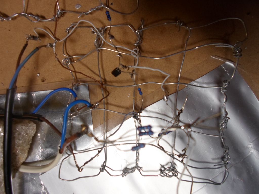
BEFORE YOU BEGIN, MAKE THE STEEL GRID
First, you make a steel grid as with the 1st radio
module. The steel grid is normally more stable if you
put the steel wires alternatively over and under one
another as you construct it -- with a sense of
'knitting'. Tie up variously colored plastic-isolated
thin steel wires (eg 0.6-0.7mm) of various lengths at
suitable positions intuitively decided.
COMPONENT LIST -- AUDIO MICRO-AMPLIFIER IN TWO VARIATIONS
*** 12V power supply, as good quality as one can get,
and fitted with high mf polarised capacitors with the
correct polarity (see other elsketches about this)
and such for noise reduction if need be
mentally tagged: "power supply"
*** one NPN BC547C 45 volt or more transistor
tagged: "amplifier transistor"
*** one 1k modulator
"amplifier power"
*** one 2.2k modulator
"amplifier e-pin"
*** one 69nf capacitor
"output capacitor" (see note elsewhere on
this page as for possible variation of this)
*** for VARIATION A of the micro-amplifier:
no more modulators necessary (for info on
the two variations and how to use the
micro-amplifier see notes at the completion
of this page)
*** for VARIATION B of the micro-amplifier:
the two following modulators are also necessary:
*** one 333 ohm modulator (eg, three 1k modulators
twisted together in parallel)
"input"
*** one 1.5k modulator (eg, two 1k modulators
twisted together in parallel, in series with one
more 1k modulator)
"amplifier m-pin"
*** Connector wires going to this elsketch:
"power supply plus wire"
"power supply ground wire" (also called e-pole)
"input main wire"
"input ground wire"
"output main wire"
"output ground wire"
TINNING INSTRUCTIONS -- AUDIO MICROAMPLIFIER
Standard recommendations: Pls read comments after the
tinning instructions BEFORE tinning. Take extra care
with getting transistors and mf capacitors right.
Switch power on only after looking at the elsketch
very very carefully -- and then keep SAFE distance!
This is your own responsibility. Don't do it if
you're uncertain about the effects of doing this!
Use much light & magnifiers. Regard names of sections
of an elsketch as informal just like item tags. Check
tinnings by pulling a little on them and when in
doubt also check with an ohm-meter before power is on
(after short-circuiting any mf capacitors connected).
Remember that unless otherwise stated you can improvise
freely as to just how you tin something to something
else -- anywhere along a wire already tinned to one of
them you can un-insulated by the tinner, say, -- it's
not that you have to put more than one wire to each
component. Don't overheat transistors and such -- a
brief tinning to a wire, and let each cool before next
tinning. If a twisted pair of modulators (say) seems
not to be tight enough, it's best to tin them also.
* Get the POWER SUPPLY wires and be sure of which wire
is which, and get them tinned to suitable wires of
different color with some length on the grid. (Cfr
notes about power supplies for other modules below.)
* Tin the INPUT GROUND WIRE to the POWER SUPPLY GROUND
WIRE and to the OUTPUT GROUND WIRE.
* Tin the OUTPUT CAPACITOR to the OUTPUT MAIN WIRE and
the other pin of this capacitor to C-PIN of the
AMPLIFIER TRANSISTOR. The size of this capacitor can be
increased to allow more bass (deeper, slower frequences
in the audio range).
* Tin the POWER SUPPLY GROUND WIRE to the AMPLIFIER
E-PIN MODULATOR, and the other pin of this modulator
to the E-PIN of the OSCILLATOR TRANSISTOR.
* Tin INPUT MAIN WIRE -- for variation A -- directly to
the M-PIN of the AMPLIFIER TRANSISTOR. This completes
the microamplifier in the Variation A case.
-- For MICRO-AMPLIFIER VARIATION B instead do this:
Tin INPUT MAIN WIRE instead to the INPUT MODULATOR,
and tin the other pin of this modulator to the M-PIN
of the AMPLIFIER TRANSISTOR. Further, also for variation B,
Tin AMPLIFIER M-PIN MODULATOR to the M-PIN of the
AMPLIFIER TRANSISTOR and tin the other pin of this
modulator to POWER SUPPLY PLUS WIRE. This enables
inputs with a different volt/ohm scheme than e.g.
the output from the 1st radio module to be properly
'listened to' by the transistor here. Note that when
you test the variation A, tapping the main input wire
with a finger without ground input wire connected will
usually lead to a slight tap in the loadspeakers (when
these are connected to a full amplifier which again is
connected to this microamplifier); but in Variation B,
no such tapping sound will normally be heard as there
is a requirement for an initial volt of some specific
kind to match with these modulators.
COMPONENT COMMENTS -- READ BEFORE TINNING
AS FOR TRANSISTORS
see the 1st AM MW radio description for C, M, E pins --
mentaly mnemonics for Collector, Middle pin, Emitter pin is
"CoMe Easy!" -- and this is the sequence that the data
work with the elsketch emulator on the PC has, it has
C M E as 1 2 3. Transistors, CoMe Easy!
[[[Mountable data app for input to elsketch emulator
in G15 comes as a link to a .zip here:]]]
YOU HAVE TINNED IT -- NOW GET IT UP!!!!!
What we call VARIATION A of this Micro-Amplifier module
is the easiest one, as it has an input that goes straight
into the middle pin of the transistor and that's that.
This is what you want when the input is of such a kind
as e.g. the output of the elsketch for the 1st radio
module. In such a case you'll likely use the same power
supply, and so the ground of the 1st radio module and
the ground of this micro-amplifier are naturally aligned.
Now let's be clear that when you connect one module with
transistors to another module with transistors, this has
to be done with care, and in some situations, it may
scramble a transistor or a coil or loadspeaker or
something. Loadspeakers are just coils fitted to magnets,
usually, and coils are, as we know, typically copper wire
and if this one is very skinny indeed, don't jolt too
much ampere through it. (We'll look more into this when
we make our own loudspeakers in an elsketch project.)
So unless you're willing to take some chances with your
modules, you shouldn't connect them. But if you have
tinned together such as the radio and you want to
enhance the output from it before it goes into a regular
amplifier with a loudspeaker, this can be a great way.
In such a case, you would usually choose VARIATION A,
the simplest one.
The microamp can also be a way to lead an output into
the mini-tx transmitter from a source that has different
expectations as to ohm-requirements and intensity and get
the mini-tx to work just smoothly. Usually, you would then
choose VARIATION B. Note that there is some volt flow
back from the microamplifier that source of sound. If the
equipment is excessively sensitive, this volt flow may
zap an item or a fuse in it. In some cases, you would want
to make the ohm-sizes of the two places VARIATION B has
modulators greater (or possibly smaller, but be careful
as more volt will flow back into the sound-outputting
equipment then).
[[[Note for those who sit around with a PC or PC laptop
with a headphone opening: yes, this has been tested and
found to work fine with Variation B: but please read the
rest of this note before doing so. First, to minimize
interference with the often ca 5-volt power supply of
the laptop, the quality of the interaction seems to
become better by running the laptop on batteries instead
of connected through power supply to the electric grid.
Secondly, anything that oscillates much about your
computer -- ethernet connection, wireless or not,
bluetooth, TV, HDTV outlet, etc etc -- anything you
can shut down of such extra electronics features of
your computer, do shut it down. Some of them may
completely and utterly reduce any connection through
headphone with sensitive equipment such as the MiniTV
to be but an amplification of noise. For instance,
a laptop connected to internet with a wire, even
if the wireless is shut off, even if the bluetooth
is shut off, may be absolutely in need of having its
plug plugged out. Other things can influence as well
-- read the notes again about getting the 1st Radio
Module up, where we recommend turning off a number of
other devices in the nearby area where you are working.
Thirdly, though we have been running this for hours
with success -- PC laptops through micro-amplifier
variation B into the mini-tx -- and using more than
one type of laptop also, in addition to testing with
other types of playing equipment -- such a setup, even
if it is tinned exactly correctly and you have a very
reliable, steady 12 volt power supply -- or better still,
a lead acid battery, with no 50 or 60 hertz rippling
noise in it -- something CAN happen to at least the
sound output part of your laptop or PC and you must be
willing to take responsibility ENTIRELY YOURSELF if you
do connect hobby electronics equipment to inputs and
outputs of consumer gadgets. Here, we can only say that,
in a situation where we have lots of backups and we have
several laptops, we took the chance and nothing
problematic happened but obviously, connecting a 12volt
driven electronics module to a place where passive
headphones or such are expected can lead to issues for
the machine. So you must take responsibility for your
machines but it is to be hoped that you find a way to
make fruitful use of the micro-amplifier with them in
a way that doesn't harm them at all! However, as said,
we give no such guarantees here. The Mini-TX
transmitter has no objection to the use of an amplifier
with several watts as input to itself, and the quality
of the result may in some cases be better than by
connecting it just from a micro-amplifier like this,
depending on the strength of the headphone outlet
of the computer. Usually, near full volume at the
PC sound control is required. This is a mono-approach
to sound, of course, so one will have to pick left or
right stereo channel, but at some PCs one may find it
possible to assert mono playing mode. See notes in
earlier mini-tx connection for how to cut into a
wire that has a jackplug in it. Note that this may
be next to impossible with the thinnest of headphone
wires -- in case, go buy a jackplug with a wire of
some more thickness. This is probably better than
buying such a tiny stereo jackplug in its bare form
as it too easily short-circuits if you tin it
directly. As said now repeatedly, you must take
responsibility for your handling of PC or what it is
that you connect any of these educational hobby
electronics modules to. And for sure, only do it
after applying extra of the normal checks that
the wires and pins don't touch too much and such.
You should also use a voltmeter on the jackplug to
measure just how much electricity you are about to
expose a consumer gadget to before plugging it into
it. Good luck!]]]
When you use many NPN transistors and let ground be
E-POLE and focus much on the PLUS of the power supply,
you have a very standard way to make modules that
increases the chances of these modules fitting well
to one another. Note however that ground -- E-POLE --
is richest in electrons, and it is fruitful that you
allow electrons to spread to the air around you; for
when you have many machines going, the air may get
somewhat electron-less, as the machines may suck
electrons out of the molecules of the air, creating
what's called 'positive ions' in the air. To counter-
balance this, you can have some metal connected to
the E-POLE of some extra power supply and let air
blow past by this metal (this is a standard ingredient
in luxury air conditioning systems). For the same reason,
when elsketches sometimes are put inside metal boxes
in some way or another, one may connect the E-POLE to
the metal of the box. This makes sense when working
with low volts such as 12, and when one is consistent
about the design of things. Note that however some
machinery -- especially engines -- may generate sparks
of much higher volts during their operations and there
may be interactions between such sparks and grounded
metal boxes, interactions that may also cause issues
of various kinds. These design considerations must
go into any electronics that is to be put to varied
and also portable use.
How was this made? A general purpose use of a transistor
must make some qualified guesses, some good guesses --
and it's important to give the transistor some room to
work without trying to squeeze all its functionality
out of it. One could imagine, for instance, having somewhat
less size of the E-PIN modulator. In some cases this would
work. But out of an interest that this module shall fit
in as many places as possible and without it easily
causing any harm, it makes sense that the modulators
aren't overly small. To fit in a transistor means that
we have to balance, to modulate, the volt so that the
input gets a little bit positive, not too positive. But
with a variation in input, this means different-sized
modulators. Theories are nice but these were found by
trying various alternatives -- but of course, as always
in our neopopperian enquiries, guided by intuition.
Note that there are other ways of achieving 'shielding'
of modules from one another than by modulators. For
instance, one can wind two coils around the same ferrite
-- creating what in 20th century jargon is called a
'transformer', but the word 'transformator' is more
to the point since all and everything is a 'transformer',
the word is too general for such a specific item like
two-or-more-coils-on-one-core. But since coils have
very few ohms to them, this require usually a clear-cut
thinking about what else to add on in the process --
usually it means more modulators. The coils may also
affect the frequencies that pass through the modulator.
The capacitor at the output also helps shielding one
module from the next. In some cases, it may be suitable
to have such a capacitor at the input as well.
Hope you got it to work like you wanted.
Best of lucks!
___________________________________________________________________
___________________________________________________________________
___________________________________________________________________
___________________________________________________________________
___________________________________________________________________
___________________________________________________________________
BACKGROUND INFO, LEGAL ASPECTS, CAREFULNESS ETC
(things which are supposed to be understood and not
repeated with each new elsketch project page)
http://www.stamash.com/secs_stamash_educational_centers/elsketch/
___________________________________________________________________
___________________________________________________________________
___________________________________________________________________
___________________________________________________________________
___________________________________________________________________
___________________________________________________________________
___________________________________________________________________
___________________________________________________________________
___________________________________________________________________
[note: for ease of composing the materials, frequent mentions
in the Elsketch texts are made of things which belong to the
future -- future Elsketch activities include making even a
whole G15 computer, and parallel activities are also referred
to in the same manner, such as the chemical educational activity
we have named Atomlite. apart from these references to things not
yet done as if they have been done, each elsketch project describes
a project actually carried out to success, and well tested, and
fully doable in the present by following the instructions.]
MICRAMP1: AUDIO MICRO-AMPLIFIER IN TWO FORMS
This is what the 1st radio module needs to become more
properly amplified before input to some amplifiers with
loudspeakers (VARIATION A); and this may be just what
you need to some sound sources to connect to the mini-tx
AM MW transmitter (VARIATION B, which can be further
varied along the lines indicated). It is a transistor,
our normal type used in plenty of elsketches, the BC547C,
wrapped up with modulators here and there and a capacitor.
Please note that when you connect modules to one another,
the voltages of these modules may interact both ways, not
just the intended ways. And so these things should fit,
and in some cases it won't be clear whether they fit
before you try it out. Read the comments at the completion
of this page before switching it on, in ANY context, thanks!
BEFORE YOU BEGIN, MAKE THE STEEL GRID
First, you make a steel grid as with the 1st radio
module. The steel grid is normally more stable if you
put the steel wires alternatively over and under one
another as you construct it -- with a sense of
'knitting'. Tie up variously colored plastic-isolated
thin steel wires (eg 0.6-0.7mm) of various lengths at
suitable positions intuitively decided.
COMPONENT LIST -- AUDIO MICRO-AMPLIFIER IN TWO VARIATIONS
*** 12V power supply, as good quality as one can get,
and fitted with high mf polarised capacitors with the
correct polarity (see other elsketches about this)
and such for noise reduction if need be
mentally tagged: "power supply"
*** one NPN BC547C 45 volt or more transistor
tagged: "amplifier transistor"
*** one 1k modulator
"amplifier power"
*** one 2.2k modulator
"amplifier e-pin"
*** one 69nf capacitor
"output capacitor" (see note elsewhere on
this page as for possible variation of this)
*** for VARIATION A of the micro-amplifier:
no more modulators necessary (for info on
the two variations and how to use the
micro-amplifier see notes at the completion
of this page)
*** for VARIATION B of the micro-amplifier:
the two following modulators are also necessary:
*** one 333 ohm modulator (eg, three 1k modulators
twisted together in parallel)
"input"
*** one 1.5k modulator (eg, two 1k modulators
twisted together in parallel, in series with one
more 1k modulator)
"amplifier m-pin"
*** Connector wires going to this elsketch:
"power supply plus wire"
"power supply ground wire" (also called e-pole)
"input main wire"
"input ground wire"
"output main wire"
"output ground wire"
TINNING INSTRUCTIONS -- AUDIO MICROAMPLIFIER
Standard recommendations: Pls read comments after the
tinning instructions BEFORE tinning. Take extra care
with getting transistors and mf capacitors right.
Switch power on only after looking at the elsketch
very very carefully -- and then keep SAFE distance!
This is your own responsibility. Don't do it if
you're uncertain about the effects of doing this!
Use much light & magnifiers. Regard names of sections
of an elsketch as informal just like item tags. Check
tinnings by pulling a little on them and when in
doubt also check with an ohm-meter before power is on
(after short-circuiting any mf capacitors connected).
Remember that unless otherwise stated you can improvise
freely as to just how you tin something to something
else -- anywhere along a wire already tinned to one of
them you can un-insulated by the tinner, say, -- it's
not that you have to put more than one wire to each
component. Don't overheat transistors and such -- a
brief tinning to a wire, and let each cool before next
tinning. If a twisted pair of modulators (say) seems
not to be tight enough, it's best to tin them also.
* Get the POWER SUPPLY wires and be sure of which wire
is which, and get them tinned to suitable wires of
different color with some length on the grid. (Cfr
notes about power supplies for other modules below.)
* Tin the INPUT GROUND WIRE to the POWER SUPPLY GROUND
WIRE and to the OUTPUT GROUND WIRE.
* Tin the OUTPUT CAPACITOR to the OUTPUT MAIN WIRE and
the other pin of this capacitor to C-PIN of the
AMPLIFIER TRANSISTOR. The size of this capacitor can be
increased to allow more bass (deeper, slower frequences
in the audio range).
* Tin the POWER SUPPLY GROUND WIRE to the AMPLIFIER
E-PIN MODULATOR, and the other pin of this modulator
to the E-PIN of the OSCILLATOR TRANSISTOR.
* Tin INPUT MAIN WIRE -- for variation A -- directly to
the M-PIN of the AMPLIFIER TRANSISTOR. This completes
the microamplifier in the Variation A case.
-- For MICRO-AMPLIFIER VARIATION B instead do this:
Tin INPUT MAIN WIRE instead to the INPUT MODULATOR,
and tin the other pin of this modulator to the M-PIN
of the AMPLIFIER TRANSISTOR. Further, also for variation B,
Tin AMPLIFIER M-PIN MODULATOR to the M-PIN of the
AMPLIFIER TRANSISTOR and tin the other pin of this
modulator to POWER SUPPLY PLUS WIRE. This enables
inputs with a different volt/ohm scheme than e.g.
the output from the 1st radio module to be properly
'listened to' by the transistor here. Note that when
you test the variation A, tapping the main input wire
with a finger without ground input wire connected will
usually lead to a slight tap in the loadspeakers (when
these are connected to a full amplifier which again is
connected to this microamplifier); but in Variation B,
no such tapping sound will normally be heard as there
is a requirement for an initial volt of some specific
kind to match with these modulators.
COMPONENT COMMENTS -- READ BEFORE TINNING
AS FOR TRANSISTORS
see the 1st AM MW radio description for C, M, E pins --
mentaly mnemonics for Collector, Middle pin, Emitter pin is
"CoMe Easy!" -- and this is the sequence that the data
work with the elsketch emulator on the PC has, it has
C M E as 1 2 3. Transistors, CoMe Easy!
[[[Mountable data app for input to elsketch emulator
in G15 comes as a link to a .zip here:]]]
YOU HAVE TINNED IT -- NOW GET IT UP!!!!!
What we call VARIATION A of this Micro-Amplifier module
is the easiest one, as it has an input that goes straight
into the middle pin of the transistor and that's that.
This is what you want when the input is of such a kind
as e.g. the output of the elsketch for the 1st radio
module. In such a case you'll likely use the same power
supply, and so the ground of the 1st radio module and
the ground of this micro-amplifier are naturally aligned.
Now let's be clear that when you connect one module with
transistors to another module with transistors, this has
to be done with care, and in some situations, it may
scramble a transistor or a coil or loadspeaker or
something. Loadspeakers are just coils fitted to magnets,
usually, and coils are, as we know, typically copper wire
and if this one is very skinny indeed, don't jolt too
much ampere through it. (We'll look more into this when
we make our own loudspeakers in an elsketch project.)
So unless you're willing to take some chances with your
modules, you shouldn't connect them. But if you have
tinned together such as the radio and you want to
enhance the output from it before it goes into a regular
amplifier with a loudspeaker, this can be a great way.
In such a case, you would usually choose VARIATION A,
the simplest one.
The microamp can also be a way to lead an output into
the mini-tx transmitter from a source that has different
expectations as to ohm-requirements and intensity and get
the mini-tx to work just smoothly. Usually, you would then
choose VARIATION B. Note that there is some volt flow
back from the microamplifier that source of sound. If the
equipment is excessively sensitive, this volt flow may
zap an item or a fuse in it. In some cases, you would want
to make the ohm-sizes of the two places VARIATION B has
modulators greater (or possibly smaller, but be careful
as more volt will flow back into the sound-outputting
equipment then).
[[[Note for those who sit around with a PC or PC laptop
with a headphone opening: yes, this has been tested and
found to work fine with Variation B: but please read the
rest of this note before doing so. First, to minimize
interference with the often ca 5-volt power supply of
the laptop, the quality of the interaction seems to
become better by running the laptop on batteries instead
of connected through power supply to the electric grid.
Secondly, anything that oscillates much about your
computer -- ethernet connection, wireless or not,
bluetooth, TV, HDTV outlet, etc etc -- anything you
can shut down of such extra electronics features of
your computer, do shut it down. Some of them may
completely and utterly reduce any connection through
headphone with sensitive equipment such as the MiniTV
to be but an amplification of noise. For instance,
a laptop connected to internet with a wire, even
if the wireless is shut off, even if the bluetooth
is shut off, may be absolutely in need of having its
plug plugged out. Other things can influence as well
-- read the notes again about getting the 1st Radio
Module up, where we recommend turning off a number of
other devices in the nearby area where you are working.
Thirdly, though we have been running this for hours
with success -- PC laptops through micro-amplifier
variation B into the mini-tx -- and using more than
one type of laptop also, in addition to testing with
other types of playing equipment -- such a setup, even
if it is tinned exactly correctly and you have a very
reliable, steady 12 volt power supply -- or better still,
a lead acid battery, with no 50 or 60 hertz rippling
noise in it -- something CAN happen to at least the
sound output part of your laptop or PC and you must be
willing to take responsibility ENTIRELY YOURSELF if you
do connect hobby electronics equipment to inputs and
outputs of consumer gadgets. Here, we can only say that,
in a situation where we have lots of backups and we have
several laptops, we took the chance and nothing
problematic happened but obviously, connecting a 12volt
driven electronics module to a place where passive
headphones or such are expected can lead to issues for
the machine. So you must take responsibility for your
machines but it is to be hoped that you find a way to
make fruitful use of the micro-amplifier with them in
a way that doesn't harm them at all! However, as said,
we give no such guarantees here. The Mini-TX
transmitter has no objection to the use of an amplifier
with several watts as input to itself, and the quality
of the result may in some cases be better than by
connecting it just from a micro-amplifier like this,
depending on the strength of the headphone outlet
of the computer. Usually, near full volume at the
PC sound control is required. This is a mono-approach
to sound, of course, so one will have to pick left or
right stereo channel, but at some PCs one may find it
possible to assert mono playing mode. See notes in
earlier mini-tx connection for how to cut into a
wire that has a jackplug in it. Note that this may
be next to impossible with the thinnest of headphone
wires -- in case, go buy a jackplug with a wire of
some more thickness. This is probably better than
buying such a tiny stereo jackplug in its bare form
as it too easily short-circuits if you tin it
directly. As said now repeatedly, you must take
responsibility for your handling of PC or what it is
that you connect any of these educational hobby
electronics modules to. And for sure, only do it
after applying extra of the normal checks that
the wires and pins don't touch too much and such.
You should also use a voltmeter on the jackplug to
measure just how much electricity you are about to
expose a consumer gadget to before plugging it into
it. Good luck!]]]
When you use many NPN transistors and let ground be
E-POLE and focus much on the PLUS of the power supply,
you have a very standard way to make modules that
increases the chances of these modules fitting well
to one another. Note however that ground -- E-POLE --
is richest in electrons, and it is fruitful that you
allow electrons to spread to the air around you; for
when you have many machines going, the air may get
somewhat electron-less, as the machines may suck
electrons out of the molecules of the air, creating
what's called 'positive ions' in the air. To counter-
balance this, you can have some metal connected to
the E-POLE of some extra power supply and let air
blow past by this metal (this is a standard ingredient
in luxury air conditioning systems). For the same reason,
when elsketches sometimes are put inside metal boxes
in some way or another, one may connect the E-POLE to
the metal of the box. This makes sense when working
with low volts such as 12, and when one is consistent
about the design of things. Note that however some
machinery -- especially engines -- may generate sparks
of much higher volts during their operations and there
may be interactions between such sparks and grounded
metal boxes, interactions that may also cause issues
of various kinds. These design considerations must
go into any electronics that is to be put to varied
and also portable use.
How was this made? A general purpose use of a transistor
must make some qualified guesses, some good guesses --
and it's important to give the transistor some room to
work without trying to squeeze all its functionality
out of it. One could imagine, for instance, having somewhat
less size of the E-PIN modulator. In some cases this would
work. But out of an interest that this module shall fit
in as many places as possible and without it easily
causing any harm, it makes sense that the modulators
aren't overly small. To fit in a transistor means that
we have to balance, to modulate, the volt so that the
input gets a little bit positive, not too positive. But
with a variation in input, this means different-sized
modulators. Theories are nice but these were found by
trying various alternatives -- but of course, as always
in our neopopperian enquiries, guided by intuition.
Note that there are other ways of achieving 'shielding'
of modules from one another than by modulators. For
instance, one can wind two coils around the same ferrite
-- creating what in 20th century jargon is called a
'transformer', but the word 'transformator' is more
to the point since all and everything is a 'transformer',
the word is too general for such a specific item like
two-or-more-coils-on-one-core. But since coils have
very few ohms to them, this require usually a clear-cut
thinking about what else to add on in the process --
usually it means more modulators. The coils may also
affect the frequencies that pass through the modulator.
The capacitor at the output also helps shielding one
module from the next. In some cases, it may be suitable
to have such a capacitor at the input as well.
Hope you got it to work like you wanted.
Best of lucks!
___________________________________________________________________
___________________________________________________________________
___________________________________________________________________
___________________________________________________________________
___________________________________________________________________
___________________________________________________________________
BACKGROUND INFO, LEGAL ASPECTS, CAREFULNESS ETC
(things which are supposed to be understood and not
repeated with each new elsketch project page)
http://www.stamash.com/secs_stamash_educational_centers/elsketch/
___________________________________________________________________
___________________________________________________________________
___________________________________________________________________
___________________________________________________________________
___________________________________________________________________
___________________________________________________________________
___________________________________________________________________
___________________________________________________________________
___________________________________________________________________