BACKGROUND INFO, LEGAL ASPECTS, CAREFULNESS ETC
(things which are supposed to be understood and not
repeated with each new elsketch project page)
http://www.stamash.com/secs_stamash_educational_centers/elsketch/
OVERVIEW OVER ONLINE AVAILABLE ELSKETCH PROJECTS --
http://www.stamash.com/secs_stamash_educational_centers/elsketch/sitemap/
-- THESE HAVE ALL BEEN CAREFULLY STUDIED IN REAL LIFE,
NOT JUST AS AN EMULATION ON A COMPUTER, AND FOUND TO
WORK AS PROMISED; NOTE THAT SUCH AS AM MW RADIOS IS
-- FOR ANY LONG-RANGE USE -- EXTREMELY TIED UP TO
ALL SORTS OF WEATHER CONDITIONS AND THE EXTENT TO
WHICH IT IS NIGHTTIME
___________________________________________________________________
___________________________________________________________________
___________________________________________________________________
___________________________________________________________________
___________________________________________________________________
___________________________________________________________________
For the G15 Multiversity: Background works
Also part of the Stamash Educational CenterS, SECS
For general info about G15 Yoga6dorg see also www.norskesites.org/fic3
In general terms, we might use the following
vocabulary: Each Elsketch project constitutes
also a report over successfully completed
electronics development and implementation work,
in a sense a bit of 'neopopperian research',
intended to be replicated in an improvised,
intuitive, playful way by anybody who likes
to educate herself in this way.
This report is dated September 3, 2013. For
general info about copyright confer the spirit
of honoring acknowledgements as found in our
www.yoga4d.org/cfdl.txt.
___________________________________________________________________
___________________________________________________________________
___________________________________________________________________
___________________________________________________________________
___________________________________________________________________
___________________________________________________________________
Elsketch: Mutual BDSM of two capacitors
-- Exploring the complexity of swinging slow
How to get a green signal to blink at ca 1 Hz --
with an attitude
 [note: for ease of composing the materials, frequent mentions
in the Elsketch texts are made of things which belong to the
future -- future Elsketch activities include making even a
whole G15 computer, and parallel activities are also referred
to in the same manner, such as the chemical educational activity
we have named Atomlite. apart from these references to things not
yet done as if they have been done, each elsketch project describes
a project actually carried out to success, and well tested, and
fully doable in the present by following the instructions.]
HERE'S SOME THINKING ABOUT IT FIRST
-- SKIP IT IF YOU JUST LIKE TO GET THE LED TO BLINK
When we made the Elsketch 1st radio module, and also the
Minitx radio transmitter, we put a capacitor in parallel
with a coil, right? The idea here is that a capacitor can
be charged up really really fast, and we want it to let go
of the charge in a pulse that is neither instantaneous nor
too slow but matching with that really really fast speed
quite well. And so we would like something which is kind of
short-circuiting the capacitor (that is, connecting a wire
from one pin to the other pin), but still not quite that --
for that would be instantaneous. Instead of just a wire,
we have a coil, for a coil can have a bit of slowness in
just how fast it allows things to go through it. By tuning
the coil to the capacitor, we get the core of many an
oscillator.
When we go to truly slow frequencies -- not a million pr
second, but around one pr second -- we have to look for
other solutions. A coil suitable for such a frequency would
probably need a diameter of a house, and correspondingly
many turns, and a ton of ferrite.
Imagine that we could get a capacitor to build up during
something like a second, after which it would get a chance
of about the same time where it could discharge itself.
This is within the range of possibility if we use a
capacitor not merely the size of 200 pf, nor merely one
thousand times that, namely 200 nf, but more like 50
times that again, namely 10 mf (mf here means microfarad,
but in 20th century terminology it is sometimes written
by means of a greek letter for m which looks like j and u
put together).
Is there any such mechanism? Is there any switch, any
automatic electronic switch, in among our electronics
items?
Well, we have the transistor, right? The transistor we
have used most so far -- called BC547C and of type, we
say, NPN -- happens to be so that it can also act like
a switch. If the input to the middle pin, the M-PIN, is
not positive, then nothing will be let through the
transistor, usually. But make it a little more positive,
and with ground connected to the E-PIN, and the C-PIN
connected to a power supply modulator and the to the
PLUS pole of the power supply, the transistor can be
regarded practically as a plain wire.
But the transistor is a quick item. It isn't the most
obvious that we can get a transistor to discharge a
capacitor when it is full, and also let it charge up
when it is empty. But let us double the picture: two
transistors and two capacitors with some modulators
are known to be able to some blinking, some truly
low-hertz cycling. One of these transistors serves
one of these capacitors, let's call it the "main"
capacitor; while the other of these transistor
serves the other one, which mimicks the effects of
a coil. All in all, when we wire in a green signal
led lamp with the first capacitor, we would like this
capacitor to be more or less as slowly discharged as
it was charged.
Another way to look a capacitor is this way: it is a
wire that -- as it progresses more and more in being
charged -- becomes more and more a modulator then
a big modulator then a really really big one. In order
to reverse the process we must let some ground through
to the plus side of the capacitor, and some plus through
to the ground side of the capacitor.
Often, when we have something such as microfarad
capacitor, we find that these are polarised -- they
have a plus side and a ground or what we call "E Pole"
side. It's important not to take this altogether too
literally in all circumstances. For instance, you can
perfectly well connect several types of polarised
items in series. When you do this, the rule is to
connect the plus of each to the ground of next, and
use the outermost two connectors, where you will have
one plus and one ground. The idea we need to stick
to is that while we don't have to fit the E-POLE
side of the capacitor to the E-POLE of the power
supply, we should pay attention to the fact that
the wire that typically has most plus in it, is going
to be connected to the plus of the capacitor. But
if there is a series of components, it may be that
the wire that has the most plus in it actually is
marked 'E-POLE' of that other component. We have to
look at the FLOW of the plus pole through possibly
several components, and also the FLOW of the
complementary pole, the E-POLE, which goes in the
other direction.
A polarised capacitor should ideally only be used
when we are totally sure that there cannot be, even
for an instant, a reversal of the flow. In praxis,
it is totally acceptable to use a polarised capacitor
if it is not entirely that clear-cut, but it is a
non-intense usage of the capacitor with a leaning
towards the correct polarities. If the use of the
capacitor is getting intense and the chance of
reversal of flow is bigger, one can use two of the
three pins of a transistor -- say, the C-PIN and
the M-PIN -- to rectify the current (and remove
the reversed flow part of it). If you use e.g. PNP
transistor for this purpose -- which is, in 20th
century jargon, to use a 'diod', but instead of
having a separate component for this purpose, we
can simply use the types of items we've already
become acqainted with -- then you put the E-POLE
to the M-PIN -- taking the hint from the name,
PNP (e.g. the BC557C used also in the radio), which
has 'n' for 'negative', or E-POLE in the middle.
The other pin, such as the C-PIN, will then be the
PLUS-POLE.
In the following elsketch, we then use two
polarised capacitors without apology, for it is
a nonintense use that isn't likely to do any damage
on these capacitors. We use one green signal -- led
-- in series with one transistor. The other transistor
doesn't have a led, it is simply there so that each
capacitor can work tightly together with one transistor.
When you switch on the power supply, you'll find that
it takes about a second before the led lights up. Then
it will light up and off with a cycle lasting for about
a second. (We say, "with an attitude", for it has a
slant to it!) If you mess about with it and it doesn't
work, try, with power supply 'off', to put a wire
between the two pins of one of the capacitors, and
then the other, so as to discharge and 'neutralise'
both. Then switch it on and it'll work, if it is
correctly wired and the items are still intact. Try
also using a volt-meter (the analog type, with a
moving measurement needle) at various positions to
learn about how the volt is going up and down in
pleasant slowness at various points. At other points
we disrupt the functionality of the elsketch if we
try to measure there, because there is too much
interference from the voltmeter at these points.
At any rate, what you measure won't probably
be very obviously clear! And that's FINE.
As I hope we say again and again during Elsketch work,
the map, the thought, we have of how these items work
are just indicating bits and pieces of their vast
functionality in reality. For instance, when a
capacitor discharges its content, it can get an
E-POLE stronger than even the E-POLE of the power
supply, for an instance. This is something
an analog voltmeter can show. So there's a lot to
this little elsketch.
To understand the workings of this little super-slow
oscillator more closely, let us imagine that when a
capacitor is fully uncharged, it is as good as plain
wire -- it short-circuits. And let us also imagine
that when a transistor has got a tiny but clear-cut
bit of PLUS on its M-PIN, it, too, is like a wire --
it short-circuits -- in its two other pins, the
C-PIN and E-PIN. (In both cases, we assume that the
polarities are correctly aligned.) Also, a led lamp
lets through pretty much current although it isn't
exactly like a wire, when it gets above a minimum
couple of volt and in the right direction. But let's
remember that when a capacitor discharges, it in
some senses acts like a power supply all on its own,
and strong readings may arise on a voltmeter.
If you imagine how the components are related in
your mind, taking time to digest this construction,
this elsketch, you'll see something like this: each
capacitor works very roughly every second time. It
works -- 'as a wire' only while it is charging --
but as long as it does this it flows into the M-PIN
of one of the transistors, allowing this transistor
to be in the 'open' state. So the capacitor is a
'wire' and it goes into the M-PIN of a transistor
and this too is like a 'wire'. But this means that
the C-PIN of that transistor goes pretty much
directly to the ground. So the other capacitor is
getting grounded, in other words, discharged, by
the action of the first capacitor, for the other
capacitor is connected exactly to the C-PIN. It's
like in BDSM, first I whip you while you are tied
up, then we do it in reverse. For as soon as the
other capacitor is discharged, the first one is
getting enough of it and stops its flow. And the
other capacitor will then repeat the exact same
action on the first. More or less exact the same
action, anyway, since we have a little bit variation
here between how the transistors are used. Only one
of them has a modulator at its M-PIN, and a led
green signal lamp.
In any case, I hope that -- given the idea of seeing
the open transistor as a 'wire', a directional wire --
we see the importance of having a modulator e.g.
between the C-PIN and the PLUS of the power supply.
For otherwise, we would simply send the whole
power supply PLUS electricity straight to the E-POLE,
and that's not what we should do in any case.
Practically, it makes often sense to tin in only
one wire from the power supply and let the other
wire just barely touch the proper wire in the
elsketch so that we immediately withdraw it if there
is any sign that it isn't correctly wired, or even
short-circuiting. If in doubt whether it might be
short-circuiting, instead of risking damaging the
power supply, use an ohm-meter on the input (after
discharging all and any capacitors there -- if it
less than some hundred ohms, go over it).
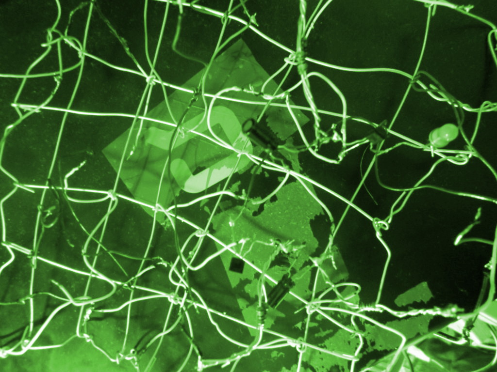
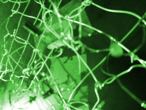
MUTU1: MUTUAL BDSM OF TWO CAPACITOR (LED BLINKER)
BEFORE YOU BEGIN, MAKE THE STEEL GRID
First, you make a steel grid as with the 1st radio
module. The steel grid is normally more stable if you
put the steel wires alternatively over and under one
another as you construct it -- with a sense of
'knitting'. Tie up variously colored plastic-isolated
thin steel wires (eg 0.6-0.7mm) of various lengths at
suitable positions intuitively decided.
COMPONENT LIST -- MUTU1
*** 12V power supply
mentally tagged: "power supply"
*** one green led indicator that will light up
at 2 or 2.1 volt or so and that can handle several
more volt; this one is polarised (see
component comments underneath)
tagged: "led"
*** one NPN BC547C 45 volt or more transistor
"blink-1 transistor"
*** one NPN BC547C 45 volt or more transistor
"blink-0 transistor"
*** one 10 mf polarised capacitor handling several
times 12 volt at least (read, if u like, theory
above about why it's ok to use polarised here)
"blink-1 input"
*** one 10 mf polarised capacitor handling several
times 12 volt at least (read, if u like, theory
above about why it's ok to use polarised here)
"blink-0 input"
*** one 50k modulator (eg, twist two 100k in parallel)
"blink-1 m-pin"
*** one 25k modulator (eg, twist four 100k in parallel)
"blink-1 power"
*** one 25k modulator (eg, twist four 100k in parallel)
"blink-0 power"
TINNING INSTRUCTIONS -- MUTU1 BLINKER
Standard recommendations: Pls read comments after the
tinning instructions BEFORE tinning. Take extra care
with getting transistors and mf capacitors right.
Switch power on only after looking at the elsketch
very very carefully -- and then keep SAFE distance!
This is your own responsibility. Don't do it if
you're uncertain about the effects of doing this!
Use much light & magnifiers. Regard names of sections
of an elsketch as informal just like item tags. Check
tinnings by pulling a little on them and when in
doubt also check with an ohm-meter before power is on
(after short-circuiting any mf capacitors connected).
Remember that unless otherwise stated you can improvise
freely as to just how you tin something to something
else -- anywhere along a wire already tinned to one of
them you can un-insulated by the tinner, say, -- it's
not that you have to put more than one wire to each
component. Don't overheat transistors and such -- a
brief tinning to a wire, and let each cool before next
tinning. If a twisted pair of modulators (say) seems
not to be tight enough, it's best to tin them also.
* Get the POWER SUPPLY wires and be sure of which wire
is which, and get them tinned to suitable wires of
different color with some length on the grid.
* Tin POWER-SUPPLY E-POLE (what we also called 'ground')
to E-PIN of LED, and the other pin of the led to BLINK-1
TRANSISTOR's E-PIN.
* Tin POWER-SUPPLY E-POLE to BLINK-0 TRANSISTOR'S E-PIN.
* Tin POWER-SUPPLY PLUS-POLE to BLINK-1 POWER modulator,
and the other pin of this modulator to C-PIN of BLINK-1
TRANSISTOR.
* Tin POWER-SUPPLY PLUS-POLE to BLINK-0 POWER modulator,
and the other pin of this modulator to C-PIN of BLINK-0
TRANSISTOR.
* Tin BLINK-1 M-PIN modulator to, guess what, M-PIN of
BLINK-1 TRANSISTOR, and the other pin of this modulator
to POWER-SUPPLY E-POLE (ground).
* We're soon done, the BLINK-1 INPUT CAPACITOR, which
is polarised, -- pick its PLUS PIN and tin this pin to
the C-PIN of BLINK-0 TRANSISTOR. The other pin of this
capacitor you put to to the 'input', that is to say,
the M-PIN of BLINK-1 TRANSISTOR.
* The BLINK-0 INPUT CAPACITOR is fitted vice versa:
its PLUS PIN goes to C-PIN of BLINK-1 TRANSISTOR. Its
other pin goes to the 'input' or M-PIN of BLINK-0
TRANSISTOR.
COMPONENT COMMENTS -- READ BEFORE TINNING
AS FOR TRANSISTORS
see the 1st AM MW radio description for C, M, E pins --
mentaly mnemonics for Collector, Middle pin, Emitter pin is
"CoMe Easy!" -- and this is the sequence that the data
work with the elsketch emulator on the PC has, it has
C M E as 1 2 3. Transistors, CoMe Easy!
This is OUR sequence, logically we might say. In practise,
check with each transistor you use what the physical
sequence of the pins are.
By the way, transistors may quickly have to be replaced
when one tries first one thing, then another, and esp.
if one has forgotten to switch power supply off. If
something appears to be totally without any meaningful
functionality, look to the transistors -- take them out
and check the 'voltage drop' as explained in one of the
first elsketches (ie, that red measurement pin on 'P'
and black on either of the 'N' pins do let volt through
but not the reverse direction, for an NPN or PNP
transistor; and that, given very precise measurement,
the voltage drop between middle pin and collector
is slightly less than between middle and emitter).
AS FOR GREEN SIGNAL LED
by 20th century conventions, the long one is usually
the one that we will bend at the middle in a straight corner
to indicate PLUS pole, so that the other pin gets more the
apparence of being the longest and the E-POLE pin. Do this.
If in doubt which pin is which, put something like two
2.2k modulators after one another in series followed by
the green signal then connect to the power supply in the
way you think is right. (Don't overload such led's with
volt esp. not the other way around; they'll light up only
in the right direction when they are intact.)
AS FOR POLARISED CAPACITORS
see theory above as to why they can be used and as to
what interpretation one can give such poles when things
are connected in such intricate ways as above. by 20th
century conventions, there may be a 'minus' (dash, -)
on the E-POLE part of them. Bend the other pin in the
middle, a straight corner (90 degrees), to indicate that
the other pin is PLUS, and let the longest be E-POLE --
you may want to bend pins of components a little apart
to reduce chance of short-circuiting them, but take care
not to apply too much pressure from the pins on the items
themselves nearest the items.
norskesites.org/fic3/fic3inf3.htm has the main #5558888
Elsketch emulation app, and it also provides this link,
which we replicate here, which formalises some of this MUTU1
work as data for the Elsketch app, app# 1115550.
YOU HAVE TINNED IT -- NOW GET IT UP!!!!!
Take care to put wires to it tentatively -- tin in
only one of them, switch on power supply, and apply
the other with all normal security precautions. Read
above how you can try various things and that you
have to discharge the capacitors to neutralise the
elsketch if you have done too much experiment and
need them to get back to normal. This is, by the way,
a feature that in one way or another we'll make use
of when it comes to making our first bits of a
digital type of ultra-mini-RAM in digital explorations
using transistor elsketches.
Best of lucks!
___________________________________________________________________
___________________________________________________________________
___________________________________________________________________
___________________________________________________________________
___________________________________________________________________
___________________________________________________________________
BACKGROUND INFO, LEGAL ASPECTS, CAREFULNESS ETC
(things which are supposed to be understood and not
repeated with each new elsketch project page)
http://www.stamash.com/secs_stamash_educational_centers/elsketch/
___________________________________________________________________
___________________________________________________________________
___________________________________________________________________
___________________________________________________________________
___________________________________________________________________
___________________________________________________________________
___________________________________________________________________
___________________________________________________________________
___________________________________________________________________
[note: for ease of composing the materials, frequent mentions
in the Elsketch texts are made of things which belong to the
future -- future Elsketch activities include making even a
whole G15 computer, and parallel activities are also referred
to in the same manner, such as the chemical educational activity
we have named Atomlite. apart from these references to things not
yet done as if they have been done, each elsketch project describes
a project actually carried out to success, and well tested, and
fully doable in the present by following the instructions.]
HERE'S SOME THINKING ABOUT IT FIRST
-- SKIP IT IF YOU JUST LIKE TO GET THE LED TO BLINK
When we made the Elsketch 1st radio module, and also the
Minitx radio transmitter, we put a capacitor in parallel
with a coil, right? The idea here is that a capacitor can
be charged up really really fast, and we want it to let go
of the charge in a pulse that is neither instantaneous nor
too slow but matching with that really really fast speed
quite well. And so we would like something which is kind of
short-circuiting the capacitor (that is, connecting a wire
from one pin to the other pin), but still not quite that --
for that would be instantaneous. Instead of just a wire,
we have a coil, for a coil can have a bit of slowness in
just how fast it allows things to go through it. By tuning
the coil to the capacitor, we get the core of many an
oscillator.
When we go to truly slow frequencies -- not a million pr
second, but around one pr second -- we have to look for
other solutions. A coil suitable for such a frequency would
probably need a diameter of a house, and correspondingly
many turns, and a ton of ferrite.
Imagine that we could get a capacitor to build up during
something like a second, after which it would get a chance
of about the same time where it could discharge itself.
This is within the range of possibility if we use a
capacitor not merely the size of 200 pf, nor merely one
thousand times that, namely 200 nf, but more like 50
times that again, namely 10 mf (mf here means microfarad,
but in 20th century terminology it is sometimes written
by means of a greek letter for m which looks like j and u
put together).
Is there any such mechanism? Is there any switch, any
automatic electronic switch, in among our electronics
items?
Well, we have the transistor, right? The transistor we
have used most so far -- called BC547C and of type, we
say, NPN -- happens to be so that it can also act like
a switch. If the input to the middle pin, the M-PIN, is
not positive, then nothing will be let through the
transistor, usually. But make it a little more positive,
and with ground connected to the E-PIN, and the C-PIN
connected to a power supply modulator and the to the
PLUS pole of the power supply, the transistor can be
regarded practically as a plain wire.
But the transistor is a quick item. It isn't the most
obvious that we can get a transistor to discharge a
capacitor when it is full, and also let it charge up
when it is empty. But let us double the picture: two
transistors and two capacitors with some modulators
are known to be able to some blinking, some truly
low-hertz cycling. One of these transistors serves
one of these capacitors, let's call it the "main"
capacitor; while the other of these transistor
serves the other one, which mimicks the effects of
a coil. All in all, when we wire in a green signal
led lamp with the first capacitor, we would like this
capacitor to be more or less as slowly discharged as
it was charged.
Another way to look a capacitor is this way: it is a
wire that -- as it progresses more and more in being
charged -- becomes more and more a modulator then
a big modulator then a really really big one. In order
to reverse the process we must let some ground through
to the plus side of the capacitor, and some plus through
to the ground side of the capacitor.
Often, when we have something such as microfarad
capacitor, we find that these are polarised -- they
have a plus side and a ground or what we call "E Pole"
side. It's important not to take this altogether too
literally in all circumstances. For instance, you can
perfectly well connect several types of polarised
items in series. When you do this, the rule is to
connect the plus of each to the ground of next, and
use the outermost two connectors, where you will have
one plus and one ground. The idea we need to stick
to is that while we don't have to fit the E-POLE
side of the capacitor to the E-POLE of the power
supply, we should pay attention to the fact that
the wire that typically has most plus in it, is going
to be connected to the plus of the capacitor. But
if there is a series of components, it may be that
the wire that has the most plus in it actually is
marked 'E-POLE' of that other component. We have to
look at the FLOW of the plus pole through possibly
several components, and also the FLOW of the
complementary pole, the E-POLE, which goes in the
other direction.
A polarised capacitor should ideally only be used
when we are totally sure that there cannot be, even
for an instant, a reversal of the flow. In praxis,
it is totally acceptable to use a polarised capacitor
if it is not entirely that clear-cut, but it is a
non-intense usage of the capacitor with a leaning
towards the correct polarities. If the use of the
capacitor is getting intense and the chance of
reversal of flow is bigger, one can use two of the
three pins of a transistor -- say, the C-PIN and
the M-PIN -- to rectify the current (and remove
the reversed flow part of it). If you use e.g. PNP
transistor for this purpose -- which is, in 20th
century jargon, to use a 'diod', but instead of
having a separate component for this purpose, we
can simply use the types of items we've already
become acqainted with -- then you put the E-POLE
to the M-PIN -- taking the hint from the name,
PNP (e.g. the BC557C used also in the radio), which
has 'n' for 'negative', or E-POLE in the middle.
The other pin, such as the C-PIN, will then be the
PLUS-POLE.
In the following elsketch, we then use two
polarised capacitors without apology, for it is
a nonintense use that isn't likely to do any damage
on these capacitors. We use one green signal -- led
-- in series with one transistor. The other transistor
doesn't have a led, it is simply there so that each
capacitor can work tightly together with one transistor.
When you switch on the power supply, you'll find that
it takes about a second before the led lights up. Then
it will light up and off with a cycle lasting for about
a second. (We say, "with an attitude", for it has a
slant to it!) If you mess about with it and it doesn't
work, try, with power supply 'off', to put a wire
between the two pins of one of the capacitors, and
then the other, so as to discharge and 'neutralise'
both. Then switch it on and it'll work, if it is
correctly wired and the items are still intact. Try
also using a volt-meter (the analog type, with a
moving measurement needle) at various positions to
learn about how the volt is going up and down in
pleasant slowness at various points. At other points
we disrupt the functionality of the elsketch if we
try to measure there, because there is too much
interference from the voltmeter at these points.
At any rate, what you measure won't probably
be very obviously clear! And that's FINE.
As I hope we say again and again during Elsketch work,
the map, the thought, we have of how these items work
are just indicating bits and pieces of their vast
functionality in reality. For instance, when a
capacitor discharges its content, it can get an
E-POLE stronger than even the E-POLE of the power
supply, for an instance. This is something
an analog voltmeter can show. So there's a lot to
this little elsketch.
To understand the workings of this little super-slow
oscillator more closely, let us imagine that when a
capacitor is fully uncharged, it is as good as plain
wire -- it short-circuits. And let us also imagine
that when a transistor has got a tiny but clear-cut
bit of PLUS on its M-PIN, it, too, is like a wire --
it short-circuits -- in its two other pins, the
C-PIN and E-PIN. (In both cases, we assume that the
polarities are correctly aligned.) Also, a led lamp
lets through pretty much current although it isn't
exactly like a wire, when it gets above a minimum
couple of volt and in the right direction. But let's
remember that when a capacitor discharges, it in
some senses acts like a power supply all on its own,
and strong readings may arise on a voltmeter.
If you imagine how the components are related in
your mind, taking time to digest this construction,
this elsketch, you'll see something like this: each
capacitor works very roughly every second time. It
works -- 'as a wire' only while it is charging --
but as long as it does this it flows into the M-PIN
of one of the transistors, allowing this transistor
to be in the 'open' state. So the capacitor is a
'wire' and it goes into the M-PIN of a transistor
and this too is like a 'wire'. But this means that
the C-PIN of that transistor goes pretty much
directly to the ground. So the other capacitor is
getting grounded, in other words, discharged, by
the action of the first capacitor, for the other
capacitor is connected exactly to the C-PIN. It's
like in BDSM, first I whip you while you are tied
up, then we do it in reverse. For as soon as the
other capacitor is discharged, the first one is
getting enough of it and stops its flow. And the
other capacitor will then repeat the exact same
action on the first. More or less exact the same
action, anyway, since we have a little bit variation
here between how the transistors are used. Only one
of them has a modulator at its M-PIN, and a led
green signal lamp.
In any case, I hope that -- given the idea of seeing
the open transistor as a 'wire', a directional wire --
we see the importance of having a modulator e.g.
between the C-PIN and the PLUS of the power supply.
For otherwise, we would simply send the whole
power supply PLUS electricity straight to the E-POLE,
and that's not what we should do in any case.
Practically, it makes often sense to tin in only
one wire from the power supply and let the other
wire just barely touch the proper wire in the
elsketch so that we immediately withdraw it if there
is any sign that it isn't correctly wired, or even
short-circuiting. If in doubt whether it might be
short-circuiting, instead of risking damaging the
power supply, use an ohm-meter on the input (after
discharging all and any capacitors there -- if it
less than some hundred ohms, go over it).
MUTU1: MUTUAL BDSM OF TWO CAPACITOR (LED BLINKER)
BEFORE YOU BEGIN, MAKE THE STEEL GRID
First, you make a steel grid as with the 1st radio
module. The steel grid is normally more stable if you
put the steel wires alternatively over and under one
another as you construct it -- with a sense of
'knitting'. Tie up variously colored plastic-isolated
thin steel wires (eg 0.6-0.7mm) of various lengths at
suitable positions intuitively decided.
COMPONENT LIST -- MUTU1
*** 12V power supply
mentally tagged: "power supply"
*** one green led indicator that will light up
at 2 or 2.1 volt or so and that can handle several
more volt; this one is polarised (see
component comments underneath)
tagged: "led"
*** one NPN BC547C 45 volt or more transistor
"blink-1 transistor"
*** one NPN BC547C 45 volt or more transistor
"blink-0 transistor"
*** one 10 mf polarised capacitor handling several
times 12 volt at least (read, if u like, theory
above about why it's ok to use polarised here)
"blink-1 input"
*** one 10 mf polarised capacitor handling several
times 12 volt at least (read, if u like, theory
above about why it's ok to use polarised here)
"blink-0 input"
*** one 50k modulator (eg, twist two 100k in parallel)
"blink-1 m-pin"
*** one 25k modulator (eg, twist four 100k in parallel)
"blink-1 power"
*** one 25k modulator (eg, twist four 100k in parallel)
"blink-0 power"
TINNING INSTRUCTIONS -- MUTU1 BLINKER
Standard recommendations: Pls read comments after the
tinning instructions BEFORE tinning. Take extra care
with getting transistors and mf capacitors right.
Switch power on only after looking at the elsketch
very very carefully -- and then keep SAFE distance!
This is your own responsibility. Don't do it if
you're uncertain about the effects of doing this!
Use much light & magnifiers. Regard names of sections
of an elsketch as informal just like item tags. Check
tinnings by pulling a little on them and when in
doubt also check with an ohm-meter before power is on
(after short-circuiting any mf capacitors connected).
Remember that unless otherwise stated you can improvise
freely as to just how you tin something to something
else -- anywhere along a wire already tinned to one of
them you can un-insulated by the tinner, say, -- it's
not that you have to put more than one wire to each
component. Don't overheat transistors and such -- a
brief tinning to a wire, and let each cool before next
tinning. If a twisted pair of modulators (say) seems
not to be tight enough, it's best to tin them also.
* Get the POWER SUPPLY wires and be sure of which wire
is which, and get them tinned to suitable wires of
different color with some length on the grid.
* Tin POWER-SUPPLY E-POLE (what we also called 'ground')
to E-PIN of LED, and the other pin of the led to BLINK-1
TRANSISTOR's E-PIN.
* Tin POWER-SUPPLY E-POLE to BLINK-0 TRANSISTOR'S E-PIN.
* Tin POWER-SUPPLY PLUS-POLE to BLINK-1 POWER modulator,
and the other pin of this modulator to C-PIN of BLINK-1
TRANSISTOR.
* Tin POWER-SUPPLY PLUS-POLE to BLINK-0 POWER modulator,
and the other pin of this modulator to C-PIN of BLINK-0
TRANSISTOR.
* Tin BLINK-1 M-PIN modulator to, guess what, M-PIN of
BLINK-1 TRANSISTOR, and the other pin of this modulator
to POWER-SUPPLY E-POLE (ground).
* We're soon done, the BLINK-1 INPUT CAPACITOR, which
is polarised, -- pick its PLUS PIN and tin this pin to
the C-PIN of BLINK-0 TRANSISTOR. The other pin of this
capacitor you put to to the 'input', that is to say,
the M-PIN of BLINK-1 TRANSISTOR.
* The BLINK-0 INPUT CAPACITOR is fitted vice versa:
its PLUS PIN goes to C-PIN of BLINK-1 TRANSISTOR. Its
other pin goes to the 'input' or M-PIN of BLINK-0
TRANSISTOR.
COMPONENT COMMENTS -- READ BEFORE TINNING
AS FOR TRANSISTORS
see the 1st AM MW radio description for C, M, E pins --
mentaly mnemonics for Collector, Middle pin, Emitter pin is
"CoMe Easy!" -- and this is the sequence that the data
work with the elsketch emulator on the PC has, it has
C M E as 1 2 3. Transistors, CoMe Easy!
This is OUR sequence, logically we might say. In practise,
check with each transistor you use what the physical
sequence of the pins are.
By the way, transistors may quickly have to be replaced
when one tries first one thing, then another, and esp.
if one has forgotten to switch power supply off. If
something appears to be totally without any meaningful
functionality, look to the transistors -- take them out
and check the 'voltage drop' as explained in one of the
first elsketches (ie, that red measurement pin on 'P'
and black on either of the 'N' pins do let volt through
but not the reverse direction, for an NPN or PNP
transistor; and that, given very precise measurement,
the voltage drop between middle pin and collector
is slightly less than between middle and emitter).
AS FOR GREEN SIGNAL LED
by 20th century conventions, the long one is usually
the one that we will bend at the middle in a straight corner
to indicate PLUS pole, so that the other pin gets more the
apparence of being the longest and the E-POLE pin. Do this.
If in doubt which pin is which, put something like two
2.2k modulators after one another in series followed by
the green signal then connect to the power supply in the
way you think is right. (Don't overload such led's with
volt esp. not the other way around; they'll light up only
in the right direction when they are intact.)
AS FOR POLARISED CAPACITORS
see theory above as to why they can be used and as to
what interpretation one can give such poles when things
are connected in such intricate ways as above. by 20th
century conventions, there may be a 'minus' (dash, -)
on the E-POLE part of them. Bend the other pin in the
middle, a straight corner (90 degrees), to indicate that
the other pin is PLUS, and let the longest be E-POLE --
you may want to bend pins of components a little apart
to reduce chance of short-circuiting them, but take care
not to apply too much pressure from the pins on the items
themselves nearest the items.
norskesites.org/fic3/fic3inf3.htm has the main #5558888
Elsketch emulation app, and it also provides this link,
which we replicate here, which formalises some of this MUTU1
work as data for the Elsketch app, app# 1115550.
YOU HAVE TINNED IT -- NOW GET IT UP!!!!!
Take care to put wires to it tentatively -- tin in
only one of them, switch on power supply, and apply
the other with all normal security precautions. Read
above how you can try various things and that you
have to discharge the capacitors to neutralise the
elsketch if you have done too much experiment and
need them to get back to normal. This is, by the way,
a feature that in one way or another we'll make use
of when it comes to making our first bits of a
digital type of ultra-mini-RAM in digital explorations
using transistor elsketches.
Best of lucks!
___________________________________________________________________
___________________________________________________________________
___________________________________________________________________
___________________________________________________________________
___________________________________________________________________
___________________________________________________________________
BACKGROUND INFO, LEGAL ASPECTS, CAREFULNESS ETC
(things which are supposed to be understood and not
repeated with each new elsketch project page)
http://www.stamash.com/secs_stamash_educational_centers/elsketch/
___________________________________________________________________
___________________________________________________________________
___________________________________________________________________
___________________________________________________________________
___________________________________________________________________
___________________________________________________________________
___________________________________________________________________
___________________________________________________________________
___________________________________________________________________