BACKGROUND INFO, LEGAL ASPECTS, CAREFULNESS ETC
(things which are supposed to be understood and not
repeated with each new elsketch project page)
http://www.stamash.com/secs_stamash_educational_centers/elsketch/
OVERVIEW OVER ONLINE AVAILABLE ELSKETCH PROJECTS --
http://www.stamash.com/secs_stamash_educational_centers/elsketch/sitemap/
-- THESE HAVE ALL BEEN CAREFULLY STUDIED IN REAL LIFE,
NOT JUST AS AN EMULATION ON A COMPUTER, AND FOUND TO
WORK AS PROMISED; NOTE THAT SUCH AS AM MW RADIOS IS
-- FOR ANY LONG-RANGE USE -- EXTREMELY TIED UP TO
ALL SORTS OF WEATHER CONDITIONS AND THE EXTENT TO
WHICH IT IS NIGHTTIME
___________________________________________________________________
___________________________________________________________________
___________________________________________________________________
___________________________________________________________________
___________________________________________________________________
___________________________________________________________________
For the G15 Multiversity: Background works
Also part of the Stamash Educational CenterS, SECS
For general info about G15 Yoga6dorg see also www.norskesites.org/fic3
In general terms, we might use the following
vocabulary: Each Elsketch project constitutes
also a report over successfully completed
electronics development and implementation work,
in a sense a bit of 'neopopperian research',
intended to be replicated in an improvised,
intuitive, playful way by anybody who likes
to educate herself in this way.
This report is dated August 15, 2013. For
general info about copyright confer the spirit
of honoring acknowledgements as found in our
www.yoga4d.org/cfdl.txt.
___________________________________________________________________
___________________________________________________________________
___________________________________________________________________
___________________________________________________________________
___________________________________________________________________
___________________________________________________________________
Elsketch: Winding your own variable capacitors for the 1st radio module
-- unbearably easy, given some metal paper, plastic and glue,
and stuff
 [note: for ease of composing the materials, frequent mentions
in the Elsketch texts are made of things which belong to the
future -- future Elsketch activities include making even a
whole G15 computer, and parallel activities are also referred
to in the same manner, such as the chemical educational activity
we have named Atomlite. apart from these references to things not
yet done as if they have been done, each elsketch project describes
a project actually carried out to success, and well tested, and
fully doable in the present by following the instructions.]
You've got the radio, you want to loosen the prefabricated
variable capacitor and make your own. You already have read
the starting-point for this radio. You have perhaps already
played around with your own ferrite coils. I'll take the
liberty of going straight to the technicalities here, since
those other two descriptions around the 1st radio module
allowed for plenty of philosophising.
THE WAY
Cut metal paper -- thin leaf aluminium for instance, or another
type of metal that fairly easily conduct electricity -- about
the size of half a normal sheet of paper, or less, say 18 times
13 centimeter. Cut off a luxuriously large corner.
Get the type of copper wire which is composed of myriad
tiny copper threads. Rip off the isolation. Spread the
copper threads out. Get a little tin on some of them, both
sides of the copper threads, with the tinner -- just a tiny
little bit, no heavy drops (just smooth the tin along the
copper, so as to dress some of the copper threads up with tin,
it's a kind of lingerie for the long legs of the copper girl).
Put them on the metal paper -- so that you have the cleanest,
most metallic part of the metal paper facing one another except
for the isolation you're putting on it, with the wires on the
other sides. In other words, you have two very clean clear
straight metal papers near one another but they are isolated
(at least one of them must be well isolated, but since they
are thin it can be good for the strength of the whole thingy
that both of them are isolated by strong glue or plastic).
And we want to connect wires to these metal papers and we
do so by spreading out very very thin copper threads of the
type that's already typically used e.g. in higher voltage
wires. We spread them out thin so that we won't create
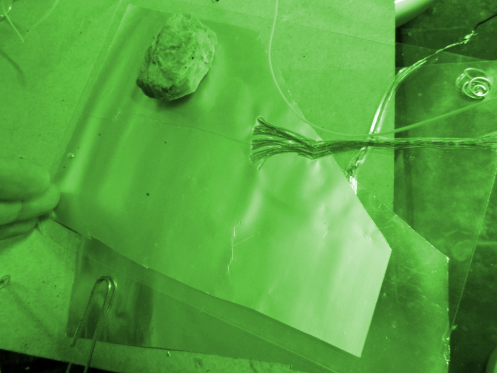
bumps in the papers. We have one wire that's absolutely
on top (see image), and another wire that's absolutely
underneath the bottom metal plate -- leaving the cleanest
clearest parallel feel of the metal plates intact, we don't
want to clutter anything.
We want to be able to move those isolated metal
plates on top of one another and then off one another, in a
gradual movement. We want the copper threads to stick firmly
to the metal, and not slide. But the metal film is usually too
thin that you can tin the copper to it, heat will burn it up.
That's why we spread it out and glue it on or push them on with
plastic around and then glue or melt the plastic to push them.
Put either loads of epoxy on one side so as to cover absolutely
all of the metal without fail, yet somewhat smoothly, or glue
plastic to it; or if you have a machine that can melt two sheets
of thin plastic to a sheet of paper then very carefully let that
machine melt the plastic around the metal paper -- with enormous
attention to the copper threads, so they don't get stuck in the
machine (there might be settings on some machines for more
flexibility as to what it is fed with). Or, if you don't have
glue, just put plastic around the metal paper, and try and tie
the copper threads very gently in some tiny holes you try and
make in the metal paper.
Not a necessity but you can then make a hole in the proper
corner and use a tool to bend some steel wire of a millimeter
so as to keep them together in just that corner -- twirl the
steel wire around and cut it so it doesn't touch any wires,
and be sure it doesn't get anywhere near the metal here --
see photo.
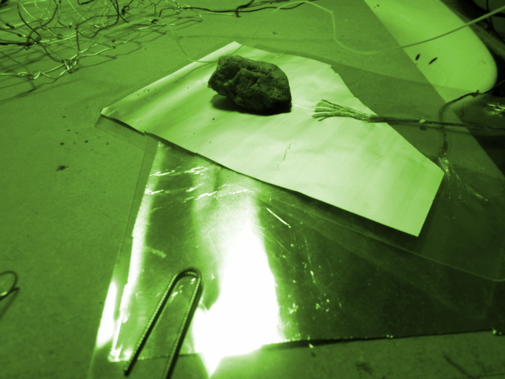
Also not a necessity in all cases but it can help to put a
heavy non-metallic object like a stone on top of the whole to
push them towards one another.
Yeah, and put some kind of clip to keep the bottommost paper
in place on the table or wherever you have your elsketch work.
We want to slide the topmost paper with the bottommost paper
being stable.
THE RESULT
It is great fun to engage in precise-tuning of the radio --
trying out different coils -- with the self-made capacitor,
if you already have got the enthusiasm going for this kind
of first-hand electronics radio and you started out using a
prefabricated variable capacitor. You'll notice that for most
coils, in most circumstances, given most types of design, the
bulk of the stations come in when the papers are slided very
much off one another -- more than in the pictures for some
coils.
But of great importance is the distance that the papers
have. When you adjust, you could adjust by having a tiny
corner of the topmost sheaf bent up -- the adjustment makes
sense if you can move the topmost sheaf without giving
pressure on it -- at least if you have sheaves that have a
little bounce in them, so that there's naturally some
air between the sheaves -- at least on the portion not
having a stone on top. The more distance the metal papers
have, the less is the capacitance, and the more the papers
must be on top of one another to give capacitance. You can
experiment with putting something like paper in between
just for fun, to sense the difference (although consider
that only an experiment, as paper shouldn't be made a
fixed part of electronics equipment because of the natural
consideration to have elements that aren't very fireprone
at all). If there's too much paper, it will decrease the
range of the capacitor too much. If the sheaves are touching
one another too much, the capacitance is so great that
it may go out of range that way. With a little bounce in
the sheaves, and the stone on the side, you can get a lot
of stability in the arrangement.
If you're doing this step by step, making the radio module
with prefabricated coils and variable capacitor, and also
with an audio module, and have just made your own coil and
your own variable capacitor, then there are two alternative
obvious next steps: make your own audio module out of
transistors, or make a own transmitter to get your own
stuff across to your radio.
Increased stability of the result: find some way to keep
the wires that goes to the rest of the radio module, tinned
to the copper threads, outside of the plates themselves. If
the wires touch the plates sometimes, dangling over like you
can see on the images on top, this dangling will tune and
retune various stations -- in addition to the sweet shift of
frequencies that always happens with MW as the belt of
blackness moves with the Sun on the other side of the planet.
As this belt of blackness moves, some stations that came
easily in before the darknest part of the night fade and
new ones come become available -- in addition to the changes
that weather conditions provide.
There is ABSOLUTELY NO REDUCTION IN QUALITY of reception when
we make our own variable capacitor this way. There is no
reduction at all -- neither of intensity nor of reception
clarity or anything else. Radio capacitors are, simply,
delightfully easy to make!
Let's note in general that since 1nf is one thousand pf, and
it takes easily five hundred nf -- five hundred thousand pf,
that is, to have an easy time working with audio amplifiers,
and they would enormously like such as 50 mf -- 50.000nf --
which is to say, 50 million picofarad -- for still better
sound effects -- we are into the need to vary materials out
of which we construct capacitors of when we go much higher
up in farads than what we did in this project. For a good
AM MW radio variable capacitor, up to some 200 pf is just
perfect, just fine, and that's probably much what you just
made, if you followed the instructions here. If you double
the size of that you are still not anywhere near 1nf. To get
all the way up to 1 mf this way we would have to fill a house
with the capacitor. Instead, the notion is that we can put
some chemical in between the two plates, or even make one of
the plates into something special, so that we get a light
chemical reaction that can preserve a little electricity for
a little while, then release it; then allow a recharging.
In this perspective, a rechargable large stable robust car
battery is like an enormously huge capacitor of many farad,
and it may be made of lead in sulphuric acid (sulphur dioxide
in water). More about such stuff in Atomlite, where we
construct all the more chemical Elsketch components.
Let's go on!
___________________________________________________________________
___________________________________________________________________
___________________________________________________________________
___________________________________________________________________
___________________________________________________________________
___________________________________________________________________
BACKGROUND INFO, LEGAL ASPECTS, CAREFULNESS ETC
(things which are supposed to be understood and not
repeated with each new elsketch project page)
http://www.stamash.com/secs_stamash_educational_centers/elsketch/
___________________________________________________________________
___________________________________________________________________
___________________________________________________________________
___________________________________________________________________
___________________________________________________________________
___________________________________________________________________
___________________________________________________________________
___________________________________________________________________
___________________________________________________________________
[note: for ease of composing the materials, frequent mentions
in the Elsketch texts are made of things which belong to the
future -- future Elsketch activities include making even a
whole G15 computer, and parallel activities are also referred
to in the same manner, such as the chemical educational activity
we have named Atomlite. apart from these references to things not
yet done as if they have been done, each elsketch project describes
a project actually carried out to success, and well tested, and
fully doable in the present by following the instructions.]
You've got the radio, you want to loosen the prefabricated
variable capacitor and make your own. You already have read
the starting-point for this radio. You have perhaps already
played around with your own ferrite coils. I'll take the
liberty of going straight to the technicalities here, since
those other two descriptions around the 1st radio module
allowed for plenty of philosophising.
THE WAY
Cut metal paper -- thin leaf aluminium for instance, or another
type of metal that fairly easily conduct electricity -- about
the size of half a normal sheet of paper, or less, say 18 times
13 centimeter. Cut off a luxuriously large corner.
Get the type of copper wire which is composed of myriad
tiny copper threads. Rip off the isolation. Spread the
copper threads out. Get a little tin on some of them, both
sides of the copper threads, with the tinner -- just a tiny
little bit, no heavy drops (just smooth the tin along the
copper, so as to dress some of the copper threads up with tin,
it's a kind of lingerie for the long legs of the copper girl).
Put them on the metal paper -- so that you have the cleanest,
most metallic part of the metal paper facing one another except
for the isolation you're putting on it, with the wires on the
other sides. In other words, you have two very clean clear
straight metal papers near one another but they are isolated
(at least one of them must be well isolated, but since they
are thin it can be good for the strength of the whole thingy
that both of them are isolated by strong glue or plastic).
And we want to connect wires to these metal papers and we
do so by spreading out very very thin copper threads of the
type that's already typically used e.g. in higher voltage
wires. We spread them out thin so that we won't create
bumps in the papers. We have one wire that's absolutely
on top (see image), and another wire that's absolutely
underneath the bottom metal plate -- leaving the cleanest
clearest parallel feel of the metal plates intact, we don't
want to clutter anything.
We want to be able to move those isolated metal
plates on top of one another and then off one another, in a
gradual movement. We want the copper threads to stick firmly
to the metal, and not slide. But the metal film is usually too
thin that you can tin the copper to it, heat will burn it up.
That's why we spread it out and glue it on or push them on with
plastic around and then glue or melt the plastic to push them.
Put either loads of epoxy on one side so as to cover absolutely
all of the metal without fail, yet somewhat smoothly, or glue
plastic to it; or if you have a machine that can melt two sheets
of thin plastic to a sheet of paper then very carefully let that
machine melt the plastic around the metal paper -- with enormous
attention to the copper threads, so they don't get stuck in the
machine (there might be settings on some machines for more
flexibility as to what it is fed with). Or, if you don't have
glue, just put plastic around the metal paper, and try and tie
the copper threads very gently in some tiny holes you try and
make in the metal paper.
Not a necessity but you can then make a hole in the proper
corner and use a tool to bend some steel wire of a millimeter
so as to keep them together in just that corner -- twirl the
steel wire around and cut it so it doesn't touch any wires,
and be sure it doesn't get anywhere near the metal here --
see photo.
Also not a necessity in all cases but it can help to put a
heavy non-metallic object like a stone on top of the whole to
push them towards one another.
Yeah, and put some kind of clip to keep the bottommost paper
in place on the table or wherever you have your elsketch work.
We want to slide the topmost paper with the bottommost paper
being stable.
THE RESULT
It is great fun to engage in precise-tuning of the radio --
trying out different coils -- with the self-made capacitor,
if you already have got the enthusiasm going for this kind
of first-hand electronics radio and you started out using a
prefabricated variable capacitor. You'll notice that for most
coils, in most circumstances, given most types of design, the
bulk of the stations come in when the papers are slided very
much off one another -- more than in the pictures for some
coils.
But of great importance is the distance that the papers
have. When you adjust, you could adjust by having a tiny
corner of the topmost sheaf bent up -- the adjustment makes
sense if you can move the topmost sheaf without giving
pressure on it -- at least if you have sheaves that have a
little bounce in them, so that there's naturally some
air between the sheaves -- at least on the portion not
having a stone on top. The more distance the metal papers
have, the less is the capacitance, and the more the papers
must be on top of one another to give capacitance. You can
experiment with putting something like paper in between
just for fun, to sense the difference (although consider
that only an experiment, as paper shouldn't be made a
fixed part of electronics equipment because of the natural
consideration to have elements that aren't very fireprone
at all). If there's too much paper, it will decrease the
range of the capacitor too much. If the sheaves are touching
one another too much, the capacitance is so great that
it may go out of range that way. With a little bounce in
the sheaves, and the stone on the side, you can get a lot
of stability in the arrangement.
If you're doing this step by step, making the radio module
with prefabricated coils and variable capacitor, and also
with an audio module, and have just made your own coil and
your own variable capacitor, then there are two alternative
obvious next steps: make your own audio module out of
transistors, or make a own transmitter to get your own
stuff across to your radio.
Increased stability of the result: find some way to keep
the wires that goes to the rest of the radio module, tinned
to the copper threads, outside of the plates themselves. If
the wires touch the plates sometimes, dangling over like you
can see on the images on top, this dangling will tune and
retune various stations -- in addition to the sweet shift of
frequencies that always happens with MW as the belt of
blackness moves with the Sun on the other side of the planet.
As this belt of blackness moves, some stations that came
easily in before the darknest part of the night fade and
new ones come become available -- in addition to the changes
that weather conditions provide.
There is ABSOLUTELY NO REDUCTION IN QUALITY of reception when
we make our own variable capacitor this way. There is no
reduction at all -- neither of intensity nor of reception
clarity or anything else. Radio capacitors are, simply,
delightfully easy to make!
Let's note in general that since 1nf is one thousand pf, and
it takes easily five hundred nf -- five hundred thousand pf,
that is, to have an easy time working with audio amplifiers,
and they would enormously like such as 50 mf -- 50.000nf --
which is to say, 50 million picofarad -- for still better
sound effects -- we are into the need to vary materials out
of which we construct capacitors of when we go much higher
up in farads than what we did in this project. For a good
AM MW radio variable capacitor, up to some 200 pf is just
perfect, just fine, and that's probably much what you just
made, if you followed the instructions here. If you double
the size of that you are still not anywhere near 1nf. To get
all the way up to 1 mf this way we would have to fill a house
with the capacitor. Instead, the notion is that we can put
some chemical in between the two plates, or even make one of
the plates into something special, so that we get a light
chemical reaction that can preserve a little electricity for
a little while, then release it; then allow a recharging.
In this perspective, a rechargable large stable robust car
battery is like an enormously huge capacitor of many farad,
and it may be made of lead in sulphuric acid (sulphur dioxide
in water). More about such stuff in Atomlite, where we
construct all the more chemical Elsketch components.
Let's go on!
___________________________________________________________________
___________________________________________________________________
___________________________________________________________________
___________________________________________________________________
___________________________________________________________________
___________________________________________________________________
BACKGROUND INFO, LEGAL ASPECTS, CAREFULNESS ETC
(things which are supposed to be understood and not
repeated with each new elsketch project page)
http://www.stamash.com/secs_stamash_educational_centers/elsketch/
___________________________________________________________________
___________________________________________________________________
___________________________________________________________________
___________________________________________________________________
___________________________________________________________________
___________________________________________________________________
___________________________________________________________________
___________________________________________________________________
___________________________________________________________________